
OK, let’s start with the hardware design.
The system will involve three sensor modules and one central controller module interconnected by the existing house LAN and some pre-existing X10 home automation gear.
To keep the designs as simple as possible, all three sensors will share these characteristics:
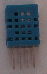
- One DHTxx-family temperature/humidity sensor
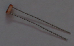
- One cadmium sulphide photoresistor
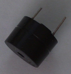
- One buzzer for warning of condensation-inducing conditions without relying on the complex, failure-prone signalling path through the normal LAN-based reporting interface.
However, as this is being prototyped from supplies I already have, I’m going to need to build three heterogeneous sensors.
Note: As I don’t regularly assemble these things from memory, this list may be revised as I actually do the assembly work.
Sensor #1
This sensor gets first pick of the components, so it gets all the ones that are easiest to work with and/or least overkill spec-wise.
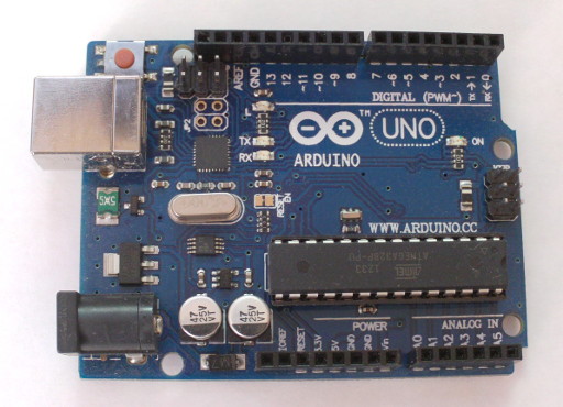
- 1 x Arduino Uno or compatible (~$11 CDN)
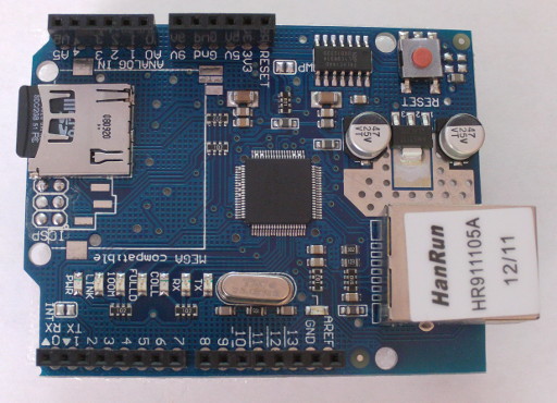
- 1 x Arduino Ethernet Shield (~$9 CDN)
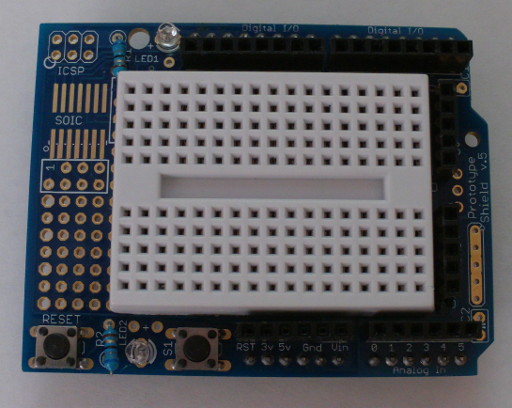
- 1 x Arduino Prototyping Shield (~$4 CDN)
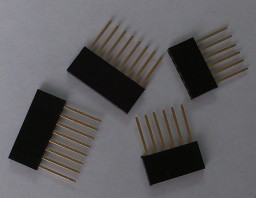
- 1 x Set of stacking headers (to allow the Protoshield to clear the RJ45 connector, ~$3 CDN if not bought in volume)
- 1 x DHT11 temperature/humidity sensor (~$1.50 CDN)
- 1 x CdS photoresistor (5.5¢ ea. in a 20-pack)
- 1 x 5V magnetic buzzer ($1.5 CDN for 5 or $1.75 CDN for 10)
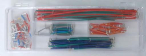
- 1 x breadboard hookup wire kit (~$3.50 CDN shared across the whole project)
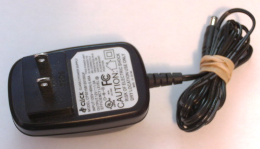
- 1 x 12VDC 1A power supply
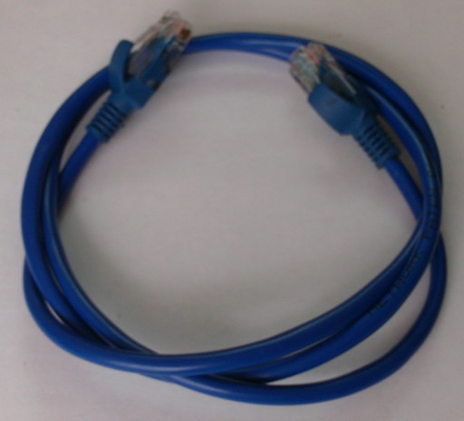
- 1 x Cat-5 Ethernet patch cable
…plus standoffs to keep it from electrically contacting the floor since this is the sensor which will be used where condensation is a concern.
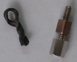
(Specifically, three 10mm hexagonal female-female standoffs to act as legs and one stacked pair of shorter male-female standoffs and a twist-tie for the remaining mounting hole since I lack a machine screw with a head small enough to fit nicely next to the SCL header on the Arduino revision 3 layout.)
Sensor #2
This sensor gets the remaining network-capable components.
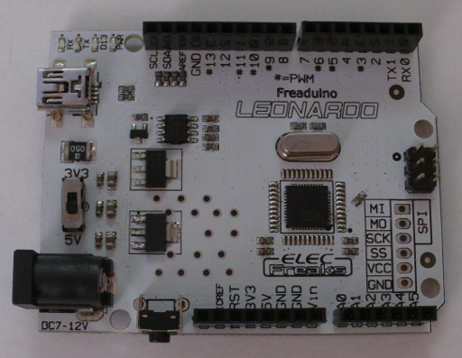
- 1 x Freaduino Leonardo or compatible (~$13 CDN)
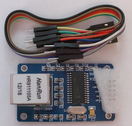
- 1 x ENC28J60 Ethernet Module (~$4 CDN)
- 1 x Arduino Prototyping Shield (~$4 CDN)
- 1 x DHT11 temperature/humidity sensor (~$1.50 CDN)
- 1 x CdS photoresistor (5.5¢ ea. in a 20-pack)
- 1 x 5V magnetic buzzer ($1.5 CDN for 5 or $1.75 CDN for 10)
- 1 x breadboard hookup wire kit (~$3.50 CDN shared across the whole project)
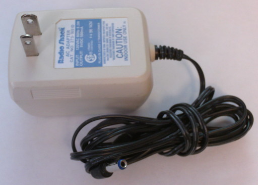
- 1 x 9VDC 500mA power supply
- 10 ft. Category 3 telephone wire
- 1 x Cat-5 Ethernet patch cable
The telephone wire is necessary for running the floor humidity and window light level sensors off the same node due to a shortage of Ethernet modules.
No standoffs are necessary for this sensor since it will be resting on an unfinished wooden surface.
Sensor #3
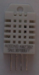
With no network adaptor modules left, this sensor connects to the central controller directly via the USB serial interface. Also, having run out of DHT11 sensors, this one uses a more precise but more expensive DHT22 instead.
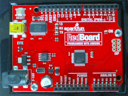
- 1 x SparkFun Redboard or compatible (~$11 CDN)
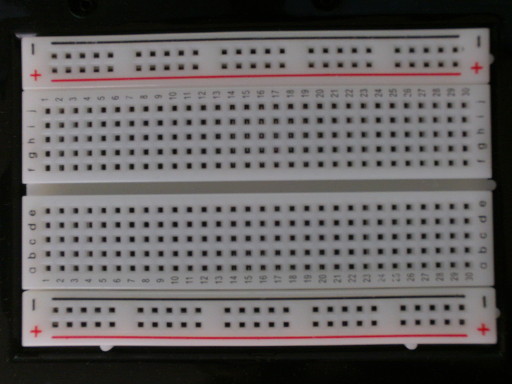
- 1 x Solderless Breadboard
- 1 x DHT22 temperature/humidity sensor ($4.50 CDN)
- 1 x CdS photoresistor (5.5¢ ea. in a 20-pack)
- 1 x 5V magnetic buzzer ($1.5 CDN for 5 or $1.75 CDN for 10)
- 1 x breadboard hookup wire kit (~$3.50 CDN shared across the whole project)
- 1 x Normally open, door-mountable magnetic switch
- 12 ft. Category 3 telephone wire
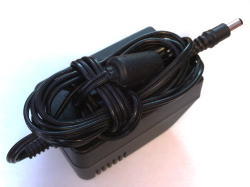
- 1 x 12VDC 1A power supply
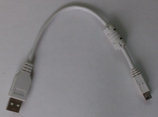
- 1 x Short USB A-to-MiniB cable
This sensor node will have the additional task of monitoring whether the door needs to be manually opened to allow the fan on X10 channel 4 to have the desired effect.
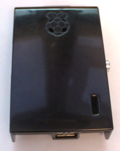
While the power supply isn’t strictly necessary, the Raspberry Pi is known for having a tendency to corrupt SD cards when supplied with insufficent power and I don’t currently have the tools and skill to determine whether that’s a concern in this configuration.
No standoffs are necessary for this sensor since it will be resting on an unfinished wooden surface.
Central Controller
- 1 x Raspberry Pi
- 1 x 5V 1A USB Micro cellphone charger
- 1 x SD Card
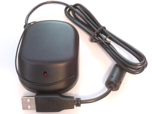
- 1 x CM19A USB X10 transceiver ($20-30 US)
- 1 x Cat-5 Ethernet patch cable
Note: Depending on how this project turns out, I may end up either using a CM17A with a USB-Serial adapter or just using my planned network-transparent architecture to pipe X10 control commands to my desktop PC which already has an X10 transceiver connected.
After all, I’ll probably be running a system node on my desktop anyway to log its internal thermal sensors and the CM17A is easier to work with on the software side… it just requires an RS-232 serial port and is very picky about which cheap Chinese USB-Serial adapters it will get along with.